- IndustriesConstruction, Machinery & Metal Manufacturing
- ApplicationsMaterial Removal, Arc Welding
- Robot SeriesBX/BT series, RA series
Robot user: KH Facilitech Co. Ltd.
System integrator: Kawaju Facilitech Co. Ltd.
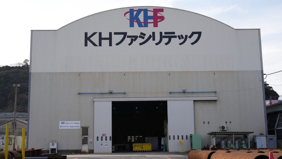
KH Facilitech Co. Ltd. are professionals in special steel frame production who focus on the production of three-dimensional shaped steel frames.
The sophisticatedly designed structural members the company creates are supporting many of the latest constructions that have been made with particular focus on their shaping. This includes the steel trusses on the large circular roof covering the stands of the new Japan National Stadium, the tower body of Tokyo Skytree, which has intertwining steel tubes reaching up to the sky, the roof of the JR Takanawa Gateway station, which envelops the terminal with a geometric silhouette like origami paper folding, and the arch-type canopy which is reminiscent of dinosaur bones in the Miyashita Park in Shibuya Ward, Tokyo.
As a company that mainly handles large-scale workpieces such as these, KH Facilitech was able to succeed in automation thanks to the existence of the KCONG software, which makes it possible to generate the robot operation data efficiently, without teaching.
Introduction background/issues :
The items processed are large-scale steel structural members for an underground tunnel
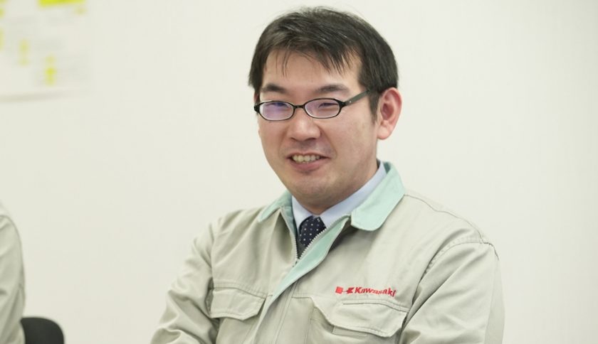
KH Facilitech are professionals in the handling of special steel and steel pipes for three-dimensional structures.
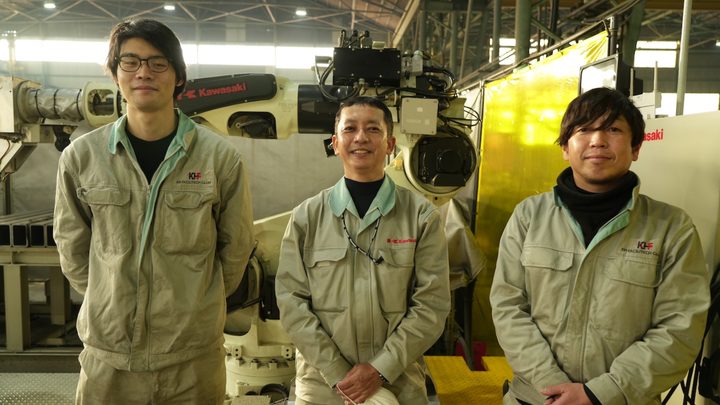
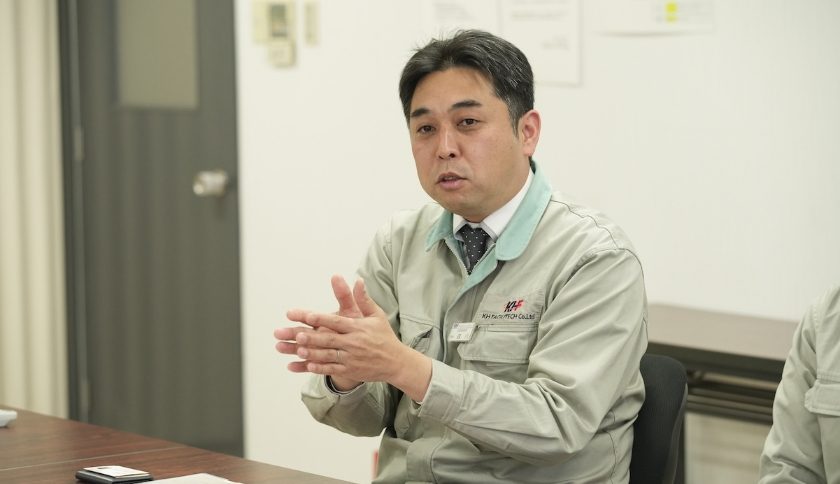
Department Manager Junichi Morikawa of KH Facilitech (Production Management Department) explained the decision to introduce robots that, “We do not often make the same thing more than once, so basically it was difficult for us to automate.
However, we decided to install robots when performing the large-scale manufacturing of steel-made segments.”
On the other hand, Leader Naoya Teraoka of Kawaju Facilitech (Equipment Engineering Division Robot Equipment Group), which has strength in the creation of robot systems with original specifications to meet the needs of customers, explains their initiatives for diverse utilization sectors as, “In recent years, we have actively worked on entering areas where labor-saving and automation are difficult.”
KH Facilitech has strength in special steel structures that create a three-dimensional structure, as used on the steel frames of the roofs of stadiums, airports, etc., bridges with an arched structure, and box girders.
Manual work by skilled workers is necessary to form these complex, three-dimensionally shaped steel structures, so the automation of the manufacturing process was previously thought to be difficult.
It was around five years ago when KH Facilitech decided to conduct the full-scale introduction of robots.
The trigger for this was an order received for the steel segments to be used in an underground tunnel.
The shield method where a cylindrical excavator is used to dig through the soil frontward is the most common construction method used for general urban tunnels.
At that time, structural materials called the segments are assembled on the walls to prevent the soil from collapsing.
In recent years, segments made of concrete have been used frequently due to their ease of working and economic efficiency. However, from the viewpoints of tensile strength, flexural durability, impact resistance and ease of working, it is thought that steel segments*1 are necessary for larger and more complex structural parts (in locations such as U-turn roads and interchanges).
KH Facilitech conducted the automation of the manufacturing process for these steel segments.
Department Manager Morikawa explained, “The introduction of robots was difficult for us because we do not handle mass-produced items.
We used them once in the past for the cutting of steel pipes, but we did not continue their use.”
However, the circular segments have a diameter easily exceeding 10 m and are divided into several pieces.
This is easy to imagine if you think about Baumkuchen divided into several pieces.
When converted to weight, the delivery of those pieces is in units of several thousand tons, so mass production is essential.
Department Manager Morikawa adds that, “Actually, we had an order for manufacturing of steel segments some16 years ago. At that time we were considering the potential methods, but it was all performed manually.” This time, we have decided to automate the process based on the past experience, and started the new mass production of steel segments.
It was decided to introduce robots to improve efficiency, stabilize quality and reduce the burden on the employees.
[Reference documents]*1:Japan Shield Segment Engineer’s Association http://jssa3.org/index.html
Introduction effects/solutions:
Original torch to realize welding with a high degree of freedom
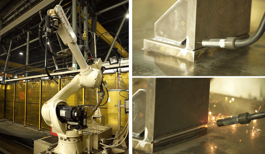
First the position of the workpiece is sensed using the wire tip, and then it is welded.
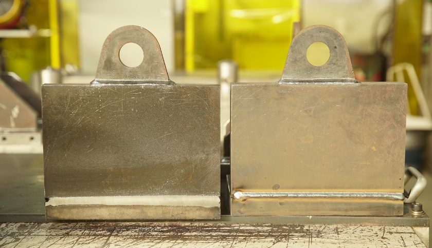
Welding processing is an area where the finish can often differ depending on the worker. However, by introducing a robot for the processing, it is possible to stabilize the quality and also to achieve a constant bead height (the convex bumps generated on the joint when welding the base material). This also leads to automation of the cutting process that follows.
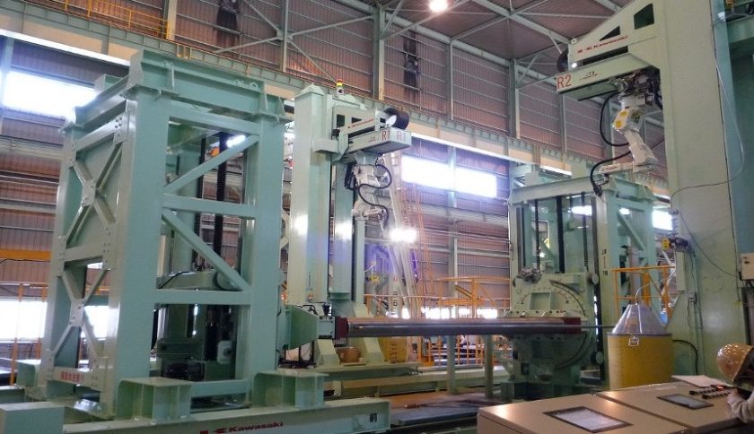
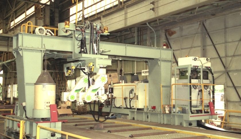
Kawaju Facilitech, which is a group of specialits for system integration, has developed various unique solutions such as portable robots and welding automation systems combining multiple robots. It integrates peripheral equipment creatively, such as travel mechanisms, movable jigs and portable devices for the efficient manufacturing of special large-scale structures such as ships and aircraft.
Building robot systems to improve the efficiency of production with large workpieces makes it necessary to have an offline teach-less system to generate programs optimal for the robot.
“This is why we have built multiple systems using the KCONG automatic teaching software for robots developed by Kawasaki. This software enables generation of the operation data for a robot on a PC from the 3D CAD data, and to perform simulations.” Saysbe Leader Teraoka.
The workpieces for this project were large steel structure of 5m long and 1m tall or larger. They weigh up to 4 to 5 tons and the lightest ones are 2 tons.
The KCONG was used effectively for the automation of the system.
Department Manager Morikawa explains that, “We introduced a robot system to the welding process first, and then to the cutting of the welding beads.
The robot can perform the welding with stable conditions (the same speed, angle and order), so the quality is stable. It can also continue working without breaks.
The welding process was previously handled by two workers, but it became possible to have just one operator, leading to labor-saving.”
In the automated line for repeated welding where welding is performed along the beveling (the groove between the base plates), a pair of vertically articulated robots, the RA010Ls equipped with traverse units are used on the both sides of the workpiece.
By installing an original long torch on a long-reach type robot, it is possible to weld workpieces with depth.
The two robots automatically perform the entire series of operations:
Cutting the tip of the wire -> cleaning the nozzle -> applying liquid to prevent spatter attachment -> sensing the position by contacting the wire with the base material -> performing multi-pass welding simultaneously from both sides of the workpiece.
Department Manager Morikawa says that, “The use of the robots made that the bead thickness constant. So, we can also automate the cutting process of the beads.
That was the suggestion by Kawaju Facilitech.” Cutting requires more manual work than welding, so the automation of the cutting process had been an issue for many years.
Assistant Section Chief Koji Hattori of Kawaju Facilitech (Equipment Engineering Division Engineering Group), who was responsible for the development, explains that, “The automation of the welding in the previous process meant that the state of the workpieces (i.e. the height of the bead) became stable, so this created the possibility that it might be possible to also apply a robot to the cutting in the following process.”
Cutting processing robot that reduced tact time by up to 25%
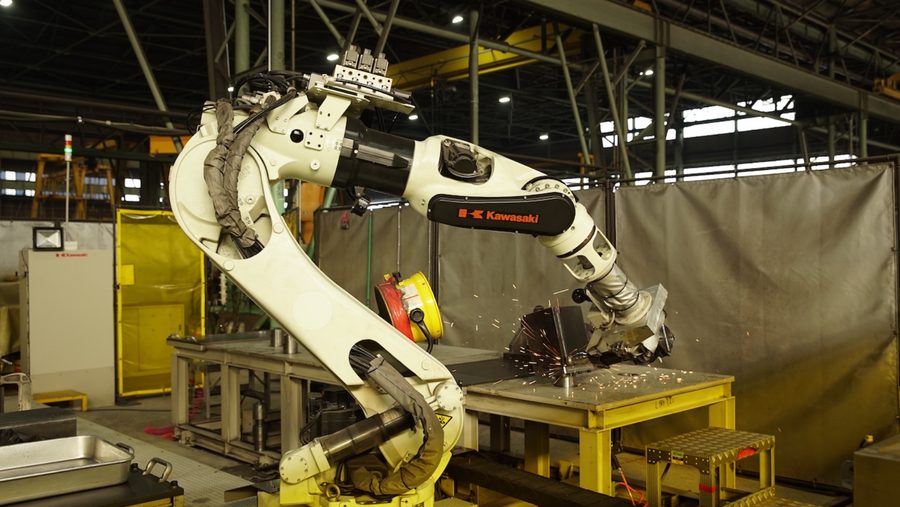
The cutting processing to finish one steel segment piece previously took one and a half days by one worker.
The automation has shortened the work time by up to 25%.
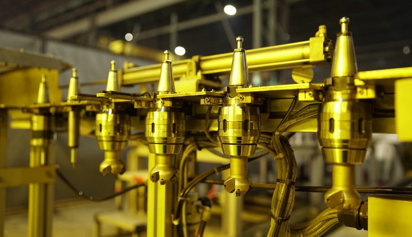
A tool changer has been used so that it is possible to use various end mills for different purposes.
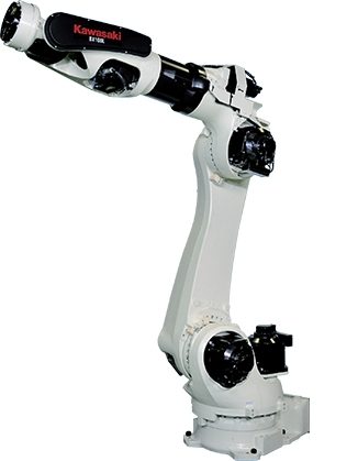
The robot selected for the weld bead cutting process was the BX200L, vertically articulated robot with a maximum payload of 200 kg.
An end mill (cutting tool) and spindle motor (rotary driving device) are attached to the hand. “A powerful robot is used to absorb the vibration and to withstand the reaction force during the cutting,” explains Assistant Section Chief Hattori.
“The system is also equipped with a function to reduce the vibration.”
The robot is installed on a traverse unit and is designed with a tool changer mechanism to enable the automatic exchange of multiple end mills and a touch probe to sense the position.
This has made it possible to perform the cutting fully automatically, with no human intervention required from the sensing before the cutting to the completion of the processing.
Assistant Section Chief Hattori explains that, “The point we most struggled with was finding the optimal solutions for all the conditions, such as the amount cut per time and the number of passes, the number of rotations of the end mill, the current value and the moving speed.
We used actual workpieces and made the adjustments.”
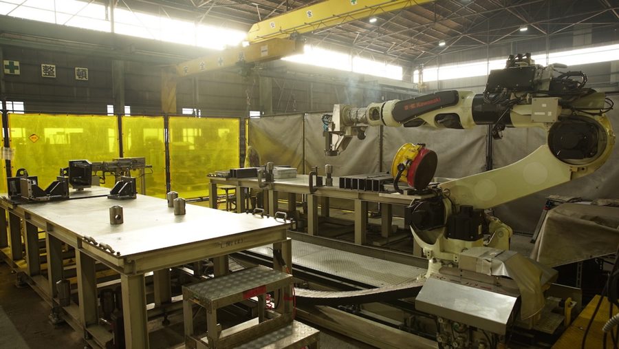
An automated cutting processing line where work benches are installed on both sides of the robot.
The automated cutting is performed in the following order.
The flow of the series of steps is:
(1) the robot moves on the traverse unit to the position of the tool changer,
(2) the dustproofing cover of the tool storage cabinet opens automatically,
(3) a touch probe for sensing is attached to the end of the arm,
(4) the touch probe is made to touch the workpiece to sense the correct position,
(5) the robot returns to the tool changer position and the probe on the end is exchanged for an end mill, and
(6) the cutting processing is implemented on the workpiece.
There is a work bench installed on both sides of the robot, so that it is possible to place two workpieces at once.
A ceiling crane is used for the movement of the large workpieces and this takes some time. If there were only one work bench, then after the completion of the cutting, it would not be possible for the robot to start the next cutting work until that workpiece was taken out.
With work benches installed on both sides of the robot, when cutting work is finished on one workpiece, it is possible for the robot to begin the cutting work on a second workpiece before that first workpiece is moved.
The ability to perform automatic cutting processing on two workpieces consecutively also means that the time required for operator support is minimized.
The automation of the cutting process reduced the tact time by up to 25% from the conventional processing.
It is also possible to perform the processing automatically during the night hours when no worker is present, so the manufacturing efficiency was dramatically improved.
“The unmanned operation also contributes to reduced overburdens on workers and improved safety.” (Department Manager Morikawa)
Future prospects and plans:
The future prospects for robots that cannot be achieved by dedicated machines
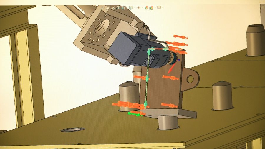
Kawaju Facilitech has built many extremely high-level systems using various travel mechanisms and elevating/turning mechanisms to robots, and even combining them with positioners (mobile jigs that can position a workpiece at the optimal angle).
It has particular strength in the creation of systems that maximize the use of the robot capabilities by using the drive motors for those travel mechanisms and positioners as external axes for the robot.
One possible method for the cutting processing for large members is to introduce a dedicated machine like a double column machining center. However, the installation of these requires massive capital investment and a large installation space.
If an automation system using a robot is used, then installation is possible in a relatively compact space. Another strength of robots is their versatility to be applicable to other workpieces if the program and peripheral equipment are changed.
Kawaju Facilitech has utilized those strengths to develop creative, unprecedented cutting automation systems.
Department Manager Morikawa says that, “Many of the customers who come on a tour of our company are interested in the cutting robot system the most.
I think processes such as cutting, grinding and polishing are an area where people in various industries and businesses worry about automation.”
Also, Assistant Section Chief Hattori explains that, “In this project, we used the automatic robot teaching software KCONG for both the welding and cutting processes, and performed everything from the equipment design to the teaching.
In the welding automation that was the first stage we struggled to customize the software.
The know-how we accumulated there enabled the cutting robot to advance smoothly from the design to the full-scale operation.” In addition, the KCONG customization was also performed with the participation of Kawasaki Technology (currently Benic Solution), a group of software development engineers.
This use of robots for the automation of the cutting process for such large workpieces was only made possible by the combination of the technologies of the three parties, with the robot development technology of Kawasaki Heavy Industries, the software technology of Kawasaki Technology, and the engineering capabilities of Kawaju Facilitech.
― Company information

Company name:
  KH Facilitech Co. Ltd.
Representative:
  President Yasuhiro Hashioka
Established:
  April 1964
Core business:
  Production and installation of steel structures such as building steel and bridges
Place of business:
  Headquarters: 9-27 Kitaminatomachi, Wakamatsu-ku, Kitakyushu-City, Fukuoka
Website:
  https://www.khf.co.jp


― System integrator company information

Company name:
  Kawaju Facilitech Co., Ltd.
Representative:
  President Yoshio Tsuchida
Established:
  January 1977
Core business:
  Various production equipment and production line design and development, large-scale mobile structure, storage tanks and piping equipment maintenance, plant facility inspection work
Place of business:
  Headquarters: Niijima-8, Harima-cho, Kako-gun, Hyogo-ken - Within Kawasaki Heavy Industries, Ltd. Harima Works
Website:
  https://www.khi.co.jp/corp/kis/


― Robots installed

[Arc welding]
Model RA010L:
  A six-axis vertically articulated robot with a long reach of 1,925 mm to easily handle large workpieces
Features:
  Compact and slim, but has a high rigidity arm, a industry-leading motionrange in its class, high dust- and water-proofing performance
Payload:
  10 kg
Axes:
  6
Positional repeatability:
  ±0.05 mm
Maximum reach:
  1,925 mm

[Cutting]
Model BX200L:
  A six-axis vertically articulated robot that realizes fast operation speeds and high density arrangement
Features:
  Compact and lightweight arm, adoption of high output/high speed motor, fast operation speed enabled by the latest vibration control.
A hollow wrist construction that accomodates wires and tubes inside the arm, enbleing small installation space.
Payload:
  200 kg
Axes:
  6
Positional repeatability:
  ±0.06 mm
Maximum reach:
  2,597 mm
