Ever wonder how a robot arm actually works?
When it comes to actually installing robots, even a slight knowledge of the structure and movement of industrial robot arms can go a long way toward a successful implementation. By knowing what’s going on inside the robot, you can better understand what the robot is capable of.
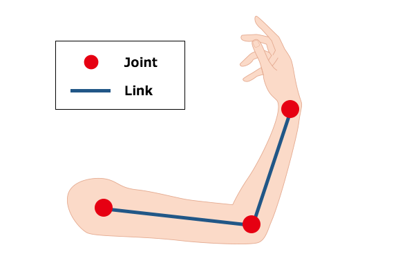
Links & Joints
Robots and humans are more alike than you may think. Humans and mechanical robots—as opposite as they may seem, share the same underlying structure of links (bones) and joints. Parts that that can freely bend and move about, such as the elbow and shoulder, are the joints, and the bones connecting those joints are equivalent to a robot’s links. The principle of moving joints and transmitting power through the links is common in both humans and robots.
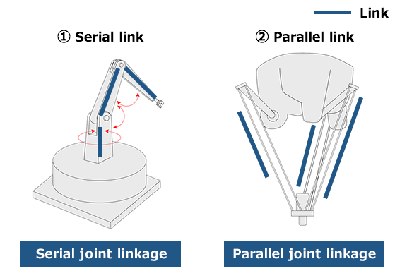
Robots are roughly categorized into two types according to how their links are arranged:
- Serial link
- Parallel link
The human arm is categorized as a serial link since its joints—the shoulder, arm and wrist—are aligned in series. Delta robots area classified as a parallel link as their joints are aligned next to each other. Industrial robots are also classified into several categories such as vertically articulated and horizontally articulated (SCARA) depending on the way the joints move and their structure.
Do the Robot
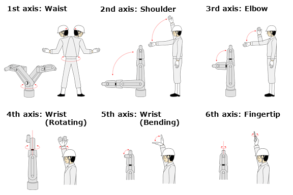
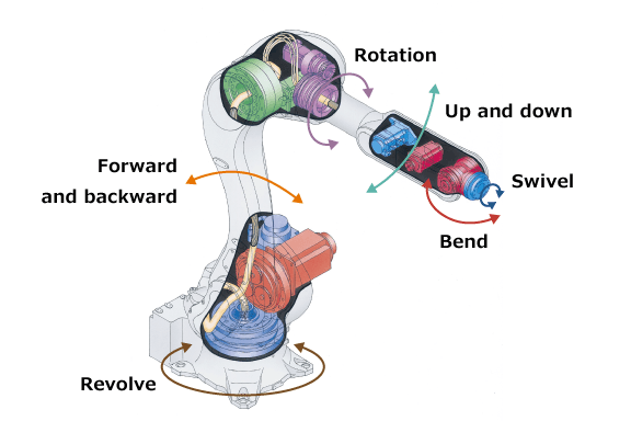
Now, let’s take a look at the movement of a vertically articulated robot, which has a similar mechanical structure to a human arm. A vertically articulated robot is an industrial robot with a serial link structure. It is generally composed of six joints (6 axes).
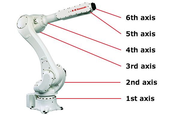
The first through third axes are the waist to the arm, and the fourth through sixth axes are the wrist to the fingertips. The first three axes carry the wrist to a specific position, and the next three axes move the wrist freely. This 6-axis construction allows robots to move freely like humans can.
What’s Inside
Next, let’s examine the internal structure of industrial robots in detail.
The illustration below shows the interior structure of Kawasaki’s small-medium payload general-purpose robot, the R series. R series robots are active across the globe in a broad range of applications, from assembly to arc welding. Since cables and harnesses can be built inside the arm, interference with peripheral equipment can be avoided and the robot can work in a small space. Its defining feature is speedy operation that can correspond to agile movements.
In this illustration you can see a robot is made up of many different parts. Among those parts are four particularly important ones: the actuator, reduction gear, encoder and transmission.
Actuators
The actuator is a component that functions as the joint of the robot. This part allows a robot to move its arm up and down or rotate, and converts energy into mechanical motions. It may be difficult to grasp this concept, but think about motors as an example of actuators. The points marked by red circles in the illustration below are the position of motors of R series:
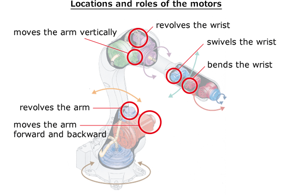
However, simple motors such as those used in plastic model kits may not be able to execute high precision movements. That’s why we use highly functional Servo motors, which can control position and speed. The most common source of energy to power actuators is electricity, but hydraulic and pneumatic energy may also be used. Some unique hydraulic-powered actuators can generate large amounts of power while retaining shock resistance.
Reduction Gears
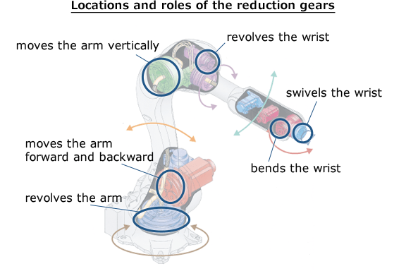
A reduction gear is a device that increases motor power. A motor alone is limited in the amount of power it can output. In order to generate more power, motors are used in combination with a reduction gear. The areas circled in blue in the following illustration are the reduction gears:
For example, bicycles have different sized gears in front and rear wheel. Generally, the transmission ( you’ll learn more about that below) is used to change the gears of the rear wheel. When a large gear is selected and the number of wheel rotations is minimized, pedaling becomes easier at the cost of speed. Riding up steep hills becomes much easier and output power can be increased. This is the same concept as reduction gears in industrial robot arms.
Encoders
An encoder is a device that indicates the position (angle) of a motor’s rotational shaft. Having an encoder can provide tangible data about how much and in what direction the robot moves. General optical encoders get their information from a disk attached to the rotating shaft of the motor. The disk has slits at regular intervals to let light pass through. There are light-emitting-diodes (LEDs) and light receiving elements (photodiodes) on both sides of the disk are to discern between light intensities (light and dark).
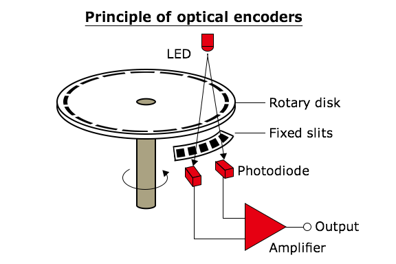
When the motor rotates, the light is either blocked or passes through the slits, so the rotation angle and speed can be determined by reading the signals. This allows Servo motors to precisely control positioning and speed.
Transmission
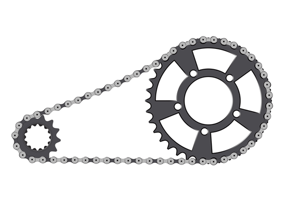
The transmission is a component that transmits the power generated by the actuators and reduction gears. The transmission is also capable of changing the direction and magnitude of power. Going back to the bicycle as an example, the chain that connects the crank to the back wheel is the transmission. Bicycles are driven by taking the rotational movement from the pedals and transferring it to the rear wheel using the transmission.
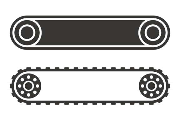
This idea is also applied to the structure of the robot. A motor used in robots is usually placed near the joints, but it can also be placed away from the joints by using transmission mechanisms such as belts and gears. Take the R series for example. These robots have compact wrists because a motor can be installed on the elbow part of the arm by the conduction mechanism.
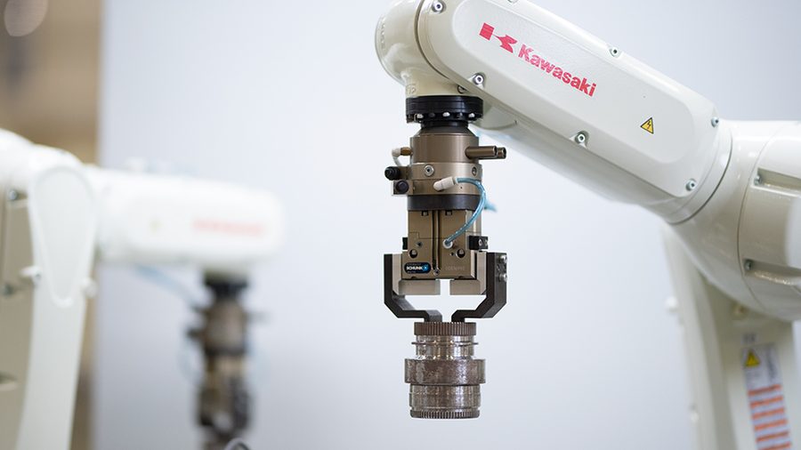
Endless Possibilities with End Effectors
Different tools allow humans to perform various tasks. In the case of industrial robots, swapping the device attached to the wrist makes a robot highly versatile, allowing them to take on a variety of jobs. This device is called an end effector, or end-of-arm tool (EOAT), and there are a wide range of them on the market. Some of them include grippers that lift up objects, vacuum (suction) types, and tools for specialized processes like welding and painting. Robots can perform practically any task by combining the flexible movement by the arm itself and task-specific end effectors.
Want to know more?
Click here to learn more about the Kawasaki Robotics product line, and what robot is right for you.